

Optimal WAMS Configuration Study for the Egyptian Grid
Written by Hady H. Fayek, and Omar H. Abdalla
The world is targeting 100% green electricity by 2050, which is turning the power system to be even more complex with a high degree of variability in terms of both generation and demand. In addition, living in the era of smart cities and energy communities, the consumer can be a part of both energy production and consumption. Therefore, the conventional techniques of measurements using point-to-point supervisory control and data acquisition (SCADA) systems will not be sufficient in smart grid applications. Consequently, Wide Area Measurement Systems (WAMS) are required for measuring voltage and current as phasors in real-time basis. In this study, an optimal WAMS configuration is applied to a model representing the 500/220 kV Egyptian grid, considering the regional boarders and the grid code with a technical and financial solution of the whole grid in different operating conditions.
Introduction
Deregulating the power system has resulted in more complexity in planning, operation, control and protection. The SCADA system in power grids should be upgraded to achieve the most favorable operation. As per the global inclination to achieve near optimum performance, the SCADA could be supplanted by WAMS (wide area measurement system). Time synchronized and time aligned phasor data from WAMS allows the following [1]:
- To see dynamics not detectible in conventional SCADA measurement systems. • Enables real event analysis by precise comparison.
- Traffic cameras monitoring transmission highways.
- Visualize traffic density as well as pattern.
- Provides early warning of trend in beginning of dynamic interaction.
- Provides root cause analysis of the events.
- Improves situational awareness.
A device that benefits from digital signal microprocessors that can measure 50/60Hz AC voltage waves and current waves, typically at a rate of 48 samples per cycle, is known as the phasor measurement unit, as shown in Figure 1 [2]. A phase-locked oscillator aligned with a GPS reference source provides the required high speed synchronized sampling with 1μs accuracy. Each site of the Phasor Measurement Unit (PMU) is calculated by the transmission frequency. This mode of phasor measurement takes place with a highly marked resolution and accuracy. The resultant time tagged phasors can be transmitted to a local or remote receiver at rates up to 0-60 samples per second based on the country code. PMUs have various sizes. Some of the larger ones can measure up to 10 phasors plus frequency, while others only measure from one to three phasors plus frequency. The PMUs are integrated to the power grid through current and voltage transformers, as shown in Figure 2 [3].
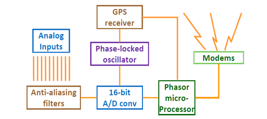
Figure 1. Phasor measurement unit block diagram [2]
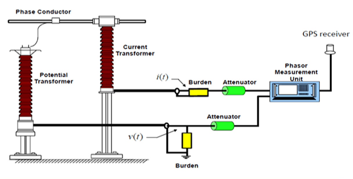
Figure 2. Integration of PMUs to the power grid [3]
Optimal WAMS Configuration for the Egyptian Grid
WAMS Components
As shown in Figure 3, the WAMS consist of the following devices:
- Phasor measurement unit.
- Phasor Data Concentrator (PDC), which can be applied as a stand-alone unit that collects data and reallocates it to other applications. The PDC functions can also be incorporated into other systems, for example monitoring/control platforms.
- Communication links that transmit data among PDCs and PMUs.
- Operator console, which is responsible for monitoring the operation in control center either at a regional or national scale.
- Data storage, which stores the data for future and evaluation.
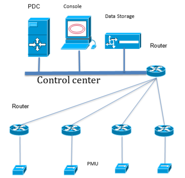
Figure 3. WAMS configuration (Provide a better figure for this!)
Proposed WAMS Configuration for the Egyptian Grid:
The Egyptian grid is modelled in [3] to simulate the real grid. The model is validated to achieve the same performance recorded by the control center at different operating conditions.
The Egyptian grid has six geographical regions, namely Cairo, Alexandria, Delta, Canal, Middle-Egypt and Upper-Egypt [4, 5]. The flow chart in Figure 4 shows the steps to achieve optimal configuration of WAMS.

Figure 4. Optimal WAMS configuration in the Egyptian grid flow chart
To allocate PMUs optimally in each region, the following optimization is applied using integer programming:
- Objective Function: Minimization of total cost
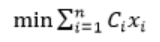 (1)
(1)
- Variables: Buses include PMUs
- Constraints: Variables at each bus should be measured by at least one PMU (K = 1) at base case or two PMUs in N-1 contingency (K = 2). K is the minimum number of PMUs that can measure the voltage at each busbar.
f(X)≥K (2)
In the constraint (2), f(X) implies that at least K PMU(s) can measure each busbar in the power system. K is a vector whose entries are all of the same value K. The PMU can measure the voltage at its own bus and the buses which are directly connected through a transmission line or a transformer to that bus. The cost of the PMU includes costs of many components, like channels, routers and communication facilities, in addition to the transportation and installation costs. Despite all of that, it can be assumed that all PMUs have the same cost except for the channels.
To allocate the PDCs optimally, the objective function in (3) is applied:
![]() (3)
(3)
Where Cfb is the installation cost of 1 km of the optical fiber links and li is the total length of the optical fiber links between the ith PMU and the PDC. Also, m is the number of PMUs installed in the network and CSw is the cost of a switch. Every CI node is one of the system buses appearing in the communication path from a PMU to the PDC. After allocating the PMU, the optimization program assumes that the PDC is allocated at each bus and the total cost of the communication will be calculated. Finally, the lowest cost indicates the optimal location of the PDC.
Results
Table 1 summarizes the results after applying the two optimization processes. The optimal configuration of the base case is illustrated in Figure 5.
Table 1: WAMS configuration in the Egyptian grid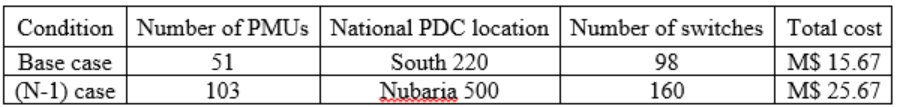
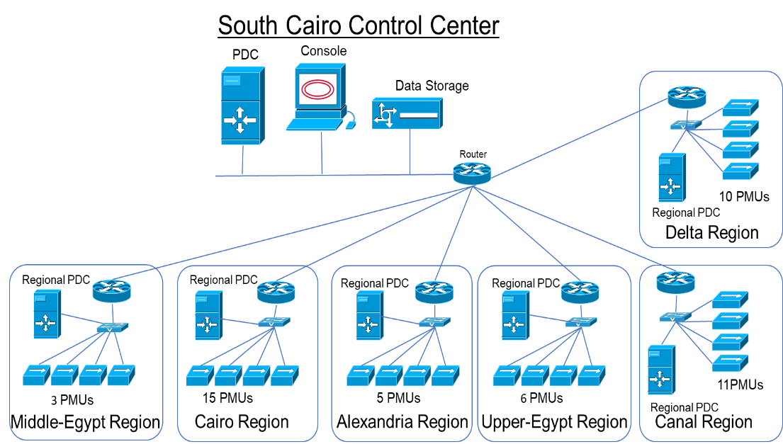
Figure 5. Optimal WAMS configuration in the Egyptian grid
Conclusion
This study illustrated the need and configuration of WAMS. It also presented a method for WAMS configuration in a real grid. The proposed method for WAMS configuration in the Egyptian power grid has provided a clear technical and financial solution of the whole grid in different operating conditions. The optimization procedure for determining the WAMS configuration has also achieved (N-2) security for the 220 kV level and (N-1) security in the 500 kV level as stated in the Egyptian grid code. The configuration of the WAMS based on contingency case will cost 63% more than the cost of the base case.
References
- H. H. Fayek, K. R. Davis, A. M. A. Ghany and O. H. Abdalla, "Configuration of WAMS and Pilot Bus Selection for Secondary Voltage Control in the Egyptian Grid," 2018 North American Power Symposium (NAPS), 2018, pp. 1-6, doi:10.1109/NAPS.2018.8600629
- M. Begovic, D. Novosel, D. Karlsson, C. Henville and G. Michel, “Wide-Area Protection and Emergency Control,” Proceedings of the IEEE, Volume 93, Issue 5, May 2005, pp. 876-891.
- O. H. Abdalla, A. M. Abdel Ghany and H. H. Fayek, "Development of a digital model of the Egyptian power grid for steady-state and transient studies", 11th International Conference on Electrical Engineering (ICEENG-11) Paper No 83-EPS. Cairo Egypt, April 2018, pp. 3-5.
- H. H. Fayek and O. H. Abdalla, "Maximization of Renewable Power Generation for Optimal Operation of the Egyptian Grid," 2020 IEEE 29th International Symposium on Industrial Electronics (ISIE), 2020, pp. 1033-1038, doi:10.1109/ISIE45063.2020.9152450
- H. H. Fayek and O. H. Abdalla, “Operation of the Egyptian Power Grid with Maximum Penetration Level of Renewable Energies Using Corona Virus Optimization Algorithm,” Smart Cities, vol. 5, no. 1, pp. 34–53, Jan. 2022.
This article was edited by Loi Lei Lai
To view all articles in this issue, please go to January 2022 eNewsletter. For a downloadable copy, please visit the IEEE Smart Cities Resource Center.


To have the eNewsletter delivered monthly to your inbox, join the IEEE Smart Cities Community.
Past Issues
To view archived articles, and issues, which deliver rich insight into the forces shaping the future of the smart cities. Older eNewsletter can be found here. To download full issues, visit the publications section of the IEEE Smart Cities Resource Center.
IEEE Smart Cities Newsletter Editors

Managing Editor

Assistant Managing Editor
IEEE Smart Cities Publications Editorial Board
Luis M. Fernandez-Ramirez
Bernard Fong
Sergii Kushch
Prasad Enjeti
Rabie Ramadan
Ramkumar Lakshminarayanan
Francesco Flammini
Fateh Krim
Maria Pia Fanti
Kristina Kunert
Vladimir Orlic
Asif Ali Ahmed R
Werbeston Oliveira
Emilio Ghiani
Shafi Khadem
Nikumani Choudhury
Mohammad Zeyad
S.M. Masum Ahmed
Payman Dehghanian
Sona N Thadevus
Kumaresan Natarajan
Lues Felipe Gaitan Cubides
Chao Shen
Balaji Sankarshanan
Chun Sing Lai
Zhang Wei
Shashikant Patil
Sai Munikoti
Akhil Jabbar Meerja
Click here for more info
Loi Lei Lai
Editor-in-Chief
IEEE Smart Cities eNewsletter